I have never built a radio before.
As a software developer I have had my share of building networking applications. Even ones that made use of WiFi or cellular networks. But I have never really understood how those radios worked at the level where software met the electromagnetic field.
I have looked into some of the lower frequency, DIY amateur stuff. Everyone seemed to be building “Manhattan-style” analog boards. That was putting me off, because I am rather clumsy with my hands, lack the patience to carefully “dead-bug” solder the parts and most importantly, I don’t really find circuits without a programmable controller attractive enough.
On the transmitting side, it ends up being fundamentally pretty simple. Just toggle a GPIO pin at the correct frequency, connect piece of wire as an antenna and get on the air. Besides the desired signal, you will pollute the spectrum with a lot of unwanted harmonics and mixing products, so add a filter or use more pins to shape your signal to more closely resemble sine wave. There is a lot more to it, but most of the complexity lies at the receiving end.
Receivers are hard.
How would one even go about building a digital receiver? And I am not talking about buying a ready-made module and connecting it to an Arduino. How would one even begin building a receiver using general purpose microcontroller from scratch?
Surprisingly, it has been done and documented multiple times before. Some super smart people who have actually made radio receivers using FPGA and some passives have left the breadcrumbs for us to follow.
The only issue is that their FPGA always had a high speed comparator to use as a 1-bit ADC. And the chip I currently enjoy messing around with does not have one. So how would one build a digital radio receiver using RP2040, heart of the Raspberry Pi Pico?
Using comparator as a part of ADC is pretty common. Couple it with a DAC to generate voltages to compare against, you can use binary search to measure input voltage like RP2040 does with it’s built-in ADC. Or generate fast, well-known slope and time when the comparator toggles. Or inject specific noise to the input and average a bunch of samples.
Sadly, we cannot use the built-in ADC, since it’s sample rate is just 500 kHz and it’s performance quickly degrades when overclocked. It’s input bandwidth is also very poor and any high frequency signals would end up so attenuated we wouldn’t be able to detect them at all.
Apart from ADC, RP2040 has digital GPIO pins that can be configured as inputs or outputs. Inputs have super high impedance, well above 1MΩ. Meaning they basically look like an open circuit to any incoming signal. Their input parasitic capacitance is minuscule, so they do not attenuate high-frequency signals a lot. There are Schmitt triggers that can be enabled or disabled, meaning the pins will either toggle cleanly with at least 100 mV of hysteresis or somewhat unpredictably without.
GPIO pins configured as outputs have selectable output impedance. The choices are approximately 100Ω, 72Ω, 50Ω and 36Ω. I say approximately, because I am mostly going by the datasheet charts here and impedance of a pin that is held high is different from one that is held low by several Ohms. There are two slew rate modes: fast and slow. Slew rate indicates how fast can the pin voltage change, but I have no idea how much they actually differ in this case.
There are also pull up/down options. According to the data sheet, the pull resistances are about 65kΩ. When both are enabled at the same time, instead of biasing the pin half way the chip switches to the bus-keep mode where the pull direction follows the last input value.
All GPIO pins can be assigned to be controlled by the CPU cores or various peripherals. Most interestingly, there are 2 programmable I/O units (PIO, with 4 State Machines each) that can service the pins at the full system clock speed. There is a 2 cycle delay between input and PIO to prevent metastability issues, though. The state machines can read, write, change pin direction, flip bits, operate input and output queues, synchronize on interrupts, have 2 scratch registers that can be compared to zero, decremented and do a lot more I am not going into right now.
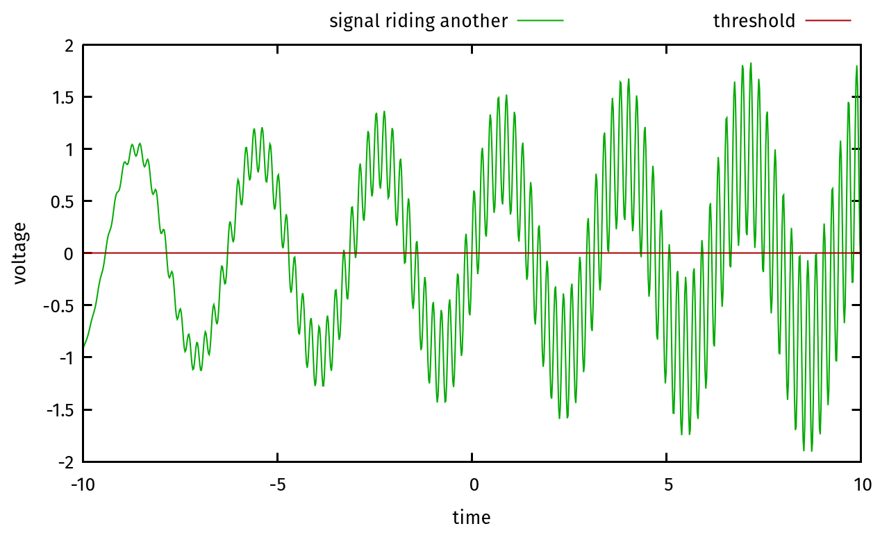
In order to build 1-bit ADC from the above, input hysteresis for the receiver GPIO pin must be disabled so that it toggles frequently at minute changes around the threshold, signal DC level must be biased as close as possible to the threshold where the GPIO pin flips between 0 and 1 and sufficient amount of uncorrelated noise must be present so that with averaging, amplitude of the signal of interest can be determined.
Imagine the signal of interest riding other signal; the time it spends at the threshold and the number of crossings it causes is proportional to its amplitude:
As for biasing the signal near the threshold, it wouldn’t be possible e.g. using resistive divider. Not only resistors are not that precise, but the threshold moves with power supply voltage and temperature. A negative feedback loop that would bias the pin by nudging it gently in the required direction is required.
Probably the most efficient way to build such a loop would be to utilize PIO. Read from the receiver pin, negate the value and output it to another pin. Then connect the two pins with a high-value resistor. I am using 1MΩ.
There are couple of problems with this arrangement, though. First of all, the biasing pin output is too strong even behind the 1MΩ resistor. Adding a 100nF capacitor to form a basic low-pass filter with the pin’s 100Ω output impedance seems to help, but I still don’t consider this really solved.
The other problem is that for really weak signals the bias is still too strong and causes various issues from unwanted oscillations that bring the signal in and out of range to adding a lot of high frequency noise. It is possible to fine-tune the average bias impedance and limit noise by turning biasing off for some portion of time. One can e.g. output bias for 1 cycle, then turn it off for 31 cycles. PIO supports extra delays and setting pin direction. Driving the bias harder for stronger signals and gently for weaker ones should mostly do the trick.
The type of receiver we are building is called Direct Sampling Receiver. Do follow the link, PySDR website is an incredibly good introduction to digital radios. I couldn’t have gotten so far without it.
The most important takeaway related to our receiver architecture is that all mixing and filtering will be performed in software. First of all, two sine waves 90° apart are required. Square waves could be used in a pinch. One wave is for the in-phase component and the other for the quadrature component. We are calling this a local oscillator, albeit a virtual one.
The incoming bits from the receiving PIO are XOR-ed with bits from the local oscillator. Why XOR? It just so happens that if you interpret 1/0 as 1/-1 and then multiply two such square waves, the results ends up being identical to what XOR does. After mixing the incoming signal with local oscillator, resulting complex waveform contain signals that were originally around the local oscillator frequency shifted down to around 0 Hz and then a whole lot of other mixing products higher up.
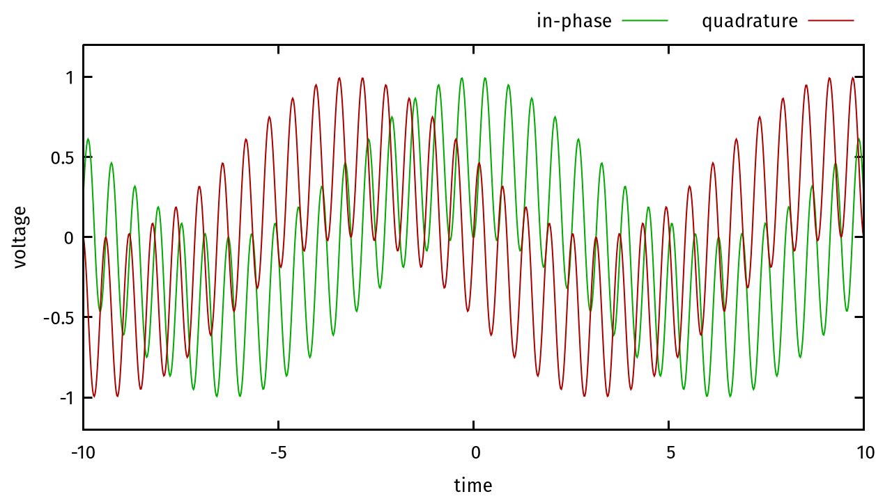
Since we are working with a complex signal here, I suggest you check out Mikael Q Kuisma’s description of the intuition behind complex radio signals. It helped me a lot. Anyway, what seems to be 0 Hz is actually the frequency we have tuned to and higher frequencies are what’s around it.
Sadly, RP2040 is not fast enough for any kind of sophisticated
filtering. But it can at least decimate waveform by summing it up, bit
by bit. As for adding the bits at such speeds, one would normally use
the popcount (population count) instruction. Since it is
not available on Cortex-M0+ cores, it would have to be simulated
otherwise. The CPUs are too slow to do it at above speeds, so one would
either have to sacrifice some of the samples for even higher noise floor
or use a different method.
It is possible to add the bits using PIO. Bits can be fed in using the TX FIFO and summed up at the full speed making use of the scratch registers and decrement instructions. In order to perform one addition per cycle or better, two bits must be processed at a time. I have used following PIO program:
0: jmp y--, 1  // 00 => -1, Y--, goto 1
1: out pc,  2  // 01 =>  0, next 2 bits
2: out pc,  2  // 10 =>  0, next 2 bits
3: jmp x--, 2  // 11 => +1, X--, goto 2
4: out pc,  2  // avoid goto 0 on first X--
It is basically a lookup table. Every out pc, 2 consumes
two bits from input and jumps to corresponding instruction. The machine
will keep decrementing X and Y indefinitely.
Provided some of the input bits end up being 01 or
10, it will consume bits faster than they are being read.
At worst, it will consume them at the same speed.
In order to get those X and Y registers
that need to be subtracted to read the summed-up amplitude, it is
necessary to inject extra instructions to copy scratch registers to the
RX FIFO periodically. Such extras will be executed instead of the saved
program which will resume afterwards. I have been using simply:
in x, 32  // output X
in y, 32  // output Y
set x, 0  // zero X
set y, 0  // zero Y
Eventually we should arrive at roughly this:
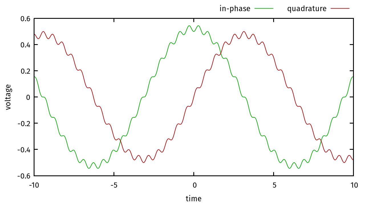
Well, that’s actually a lie. A lot of the high frequency content that was not properly filtered out will appear as part of our signal of interest, distorting it in unwanted ways. Sadly there is nothing we can do about it with the processing power of RP2040.
Here is how the system looks like from the signal processing, analog point of view. You might notice 300 Mbps. I have overclocked my Pico for better results. I recommend keeping your system clock at more than 2.5× the frequency you wish to receive. In the diagram, local oscillator is tuned to 88.2 MHz, which is one of the stronger local FM radio stations.

As for the mixing implementation, RP2040 allows writing to certain
registers using address that is 0x1000 higher. In such
case, the bits are actually XOR-ed to current register bits. With
extensive use of DMA, it is possible to automate the whole mixing and
summing process and leave the cores free for further processing, such as
filtering and secondary decimation.

DMA takes data from receiver PIO, makes two copies, XORs them with the local oscillator bits and sends them to summer PIOs. In order to obtain summer outputs at predictable rate, it is possible to send the extra instructions using DMA with the help of a pacing timer.

Further processing, such as additional filtering, can be performed in software using a circular buffer. I had to use almost all DMA channels for best performance. I hope that RP2040 successor will populate all 16 instead of just 12.
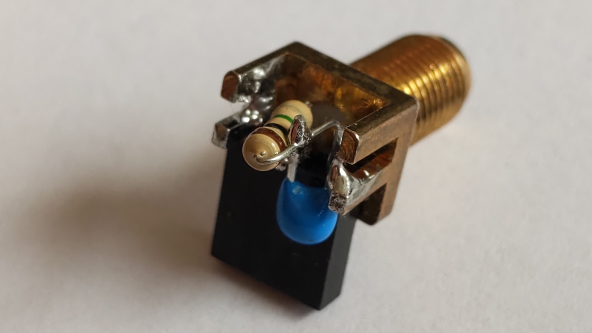
Using a piece of wire for antenna worked, but the performance was not very good. Since my extendable dipole antenna is equipped with an SMA connector, for a quick and dirty solution that integrates 100nF capacitor and 1MΩ resistor, this is what I cobbled up:
Processing the final 192 kHz stream to demodulate wideband FM in
order to produce audio is something I am not interested in coding myself
at the moment. I would probably have to learn about CORDIC to take
atan2 fast enough to demodulate FM, implement fast enough
de-emphasis filter and finally transform the waveform into differential
PDM signal to drive a speaker through a full H-bridge circuit.
So instead of doing all that, raw IQ samples are sent over USB CDC to my PC, picked up by a small Python script, turned into TCP stream and processed with GNU Radio, which provides a nice graphical application called GNU Radio Companion that can be used to construct signal processing pipelines and output the audio to the system speakers.
Yes, it’s noisy, but isn’t it still pretty cool that you can do that with a $1 general purpose microprocessor, two passive components and an antenna?
Check out the source code for all
the small details.
It’s not exactly tidy, though.
There are far better and easier approaches, to be honest. Quadrature detectors (also called Tayloe detectors) are currently the best choice for modern DIY sub-100 MHz transceivers. By performing the mixing outside the MCU, they leave the intensive filtering work to a handful of analog parts and give you the base band signal to read with a slow, high-resolution ADC. And every bit of that ADC gives you 6 dB SNR. That’s 50 dB just from the builtin Pico ADC and 100 dB if you use an external audio ADC. And you can add a super simple analog amplifier at the baseband frequency for extra gain on top of that.
This solution barely manages to receive the super loud FM stations transmitting from the same city. It can be repurposed to act as a receiver for remotely controlled toys, though. With frequency shifting or phase shifting modulations, commands at over 1 kbps can be received from up to about 40 meters outside with a simple GPIO-into-an-antenna transmitter.
mordae@anilinux.org
2024-06-04, updated 2025-03-27